概要
- 前回、Grove接続(シリアル)で受け取ってLCDに表示できるようにしたが、受信側のM5Stackの処理について単純に(1)データ受け取る→(2)LCD表示→(1)データ受け取る→・・・と順番に繰り返していたので、(1)と(2)で待ち時間が両方独立して必要だった。
- 今回は、バッファを持たせることで(1)と(2)の待ち時間を重複させてちょっとだけ早くする。
コード
送信側:Timer Camera / Unit Cam
前回と同じ
#include "esp_camera.h"

void setup() {

  // USBシリアル通信(確認用)
  Serial.begin(115200);

  // GROVEのシリアル通信
  Serial1.begin(115200, SERIAL_8N1, 13, 4); // Timer Camera / Unit Cam

  // カメラ用パラメータ(Timer Camera / Unit Cam)
  camera_config_t config;
  config.ledc_channel = LEDC_CHANNEL_0;
  config.ledc_timer   = LEDC_TIMER_0;
  config.pin_d0       = 32;
  config.pin_d1       = 35;
  config.pin_d2       = 34;
  config.pin_d3       = 5;
  config.pin_d4       = 39;
  config.pin_d5       = 18;
  config.pin_d6       = 36;
  config.pin_d7       = 19;
  config.pin_xclk     = 27;
  config.pin_pclk     = 21;
  config.pin_vsync    = 22;
  config.pin_href     = 26;
  config.pin_sccb_sda = 25;
  config.pin_sccb_scl = 23;
  config.pin_pwdn     = -1;
  config.pin_reset    = 15;
  config.xclk_freq_hz = 20000000;
  config.pixel_format = PIXFORMAT_JPEG; // jpeg出力
  config.frame_size   = FRAMESIZE_QVGA; // 320x240
  config.jpeg_quality = 30; // jpeg品質 0(高品質)~63(低品質)
  config.fb_count     = 2; // CAMERA_GRAB_LATEST設定時は2以上必要
  config.grab_mode    = CAMERA_GRAB_LATEST; // 最終フレームバッファだけを取得
  config.fb_location  = CAMERA_FB_IN_PSRAM; // PSRAM使用する(Timer Camera用)
//  config.fb_location  = CAMERA_FB_IN_DRAM; // PSRAM使用しない(Unit Cam用)

  // カメラ初期化
  esp_err_t err = esp_camera_init(&config);
  if (err != ESP_OK) {
      Serial.printf("Camera init failed with error 0x%x", err);
      return;
  }

  // 画像反転
  sensor_t *s = esp_camera_sensor_get();
  s->set_vflip(s, 1);
}

void loop() {

  // 画像取得&送信
  camera_fb_t *fb = esp_camera_fb_get();
  if (fb) {

    // データ区切り用文字列(DATA)
    Serial1.print("DATA");

    // サイズ送信
    Serial1.write((byte *)&(fb->len), 4); // size_t(int) -> byte[4]で送信

    // データ送信
    Serial1.write(fb->buf, fb->len);

    // フレームバッファ開放
    esp_camera_fb_return(fb);
  }
}
受信側:M5Stack
バッファを2つ用意して、空いてる方に入れる&入ってる方を表示するだけ。
#include <M5Stack.h>

uint8_t buf[4];
uint8_t buf1[10000];
volatile size_t data_size1 = 0;
uint8_t buf2[10000];
volatile size_t data_size2 = 0;

void setup() {

  M5.begin();

  // USBシリアル通信(確認用)
  Serial.begin(115200);

  // GROVEのシリアル通信
  Serial1.begin(115200, SERIAL_8N1, 21, 22); // PORT-A(Red)(GPIO21, GPIO22)

  // マルチタスク
  xTaskCreatePinnedToCore(subProcess, "subProcess", 4096, NULL, 1, NULL, 1);
}

void loop() {

  if (Serial1.available() > 4){

    // データ区切り用文字列(DATA)
    if (Serial1.read() == 'D') {
      if (Serial1.read() == 'A') {
        if (Serial1.read() == 'T') {
          if (Serial1.read() == 'A') {

            // サイズ取得
            Serial1.readBytes(buf, 4);
            size_t temp = buf[0] | buf[1] << 8 | buf[2] << 16 | buf[3] << 24 ; // byte[4] -> size_t(int)

            // データ取得
            while (1) {
              if (data_size1 == 0) {
                Serial1.readBytes(buf1, temp);
                data_size1 = temp;
                break;
              }
              else if (data_size2 == 0) {
                Serial1.readBytes(buf2, temp);
                data_size2 = temp;
                break;
              }
            }

          }
        }
      }
    }
  }
}

// 別タスク
void subProcess(void * pvParameters) {
  // 画面表示
  while (1) {
    if (data_size1 != 0) {
      M5.Lcd.drawJpg(buf1, data_size1, 0, 0, 320, 240);
      data_size1 = 0;
    }
    else if (data_size2 != 0) {
      M5.Lcd.drawJpg(buf2, data_size2, 0, 0, 320, 240);
      data_size2 = 0;
    }
  }
}
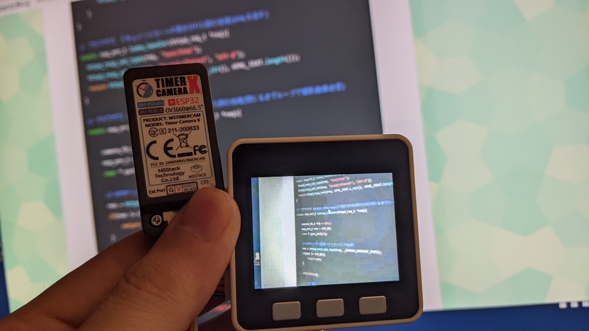
結果
- ちょっとだけ早くなった感じはする。
