2026年3月時点の光造形3Dプリンター
FDMならBambuLab買っとけば間違いないみたいなところあるんですが、光造形だとどこがいいんでしょうか・・・?
適当に調べたメモ

メーカー
| No | メーカー名 | 国 | 代表機種 | 備考 |
|---|---|---|---|---|
| 1 | ELEGOO | 中国 | Saturn 4 Ultra | MSLA方式レジンプリンターを多数展開。2020年代以降家庭用市場で出荷数が増加。 |
| 2 | Anycubic | 中国 | Photon Mono M7 Pro | Photonシリーズを継続展開。FDMとレジン両方の3Dプリンターを製造。 |
| 3 | Phrozen | 台湾 | Sonic Mighty 12K | 高解像度LCD(4K〜12K)機を早期から展開。 |
| 4 | Creality | 中国 | HALOT-MAGE S | FDMプリンター(Enderシリーズ)を含む3Dプリンター製造メーカー。HALOTブランドでMSLA機を販売。 |
| 5 | Uniformation | 中国 | GK3 Ultra | 密閉構造および内部温度管理機能を備えたMSLAプリンターを展開。 |
| 6 | Formlabs | アメリカ | Form 4 | 独自光学方式(LFS / LFD)を採用し専用材料を使用。 |
| 7 | HeyGears | 中国 | Reflex RS | ハード・ソフト・材料を統合したワークフローを提供。歯科・工業分野で使用例あり。 |
| 8 | Peopoly | 台湾 | Phenom Forge | 大型造形対応MSLAおよびレーザーSLA機を開発・販売。 |
色々あるけど聞いたことあるのは、ELEGOO、Anycubic、Crealityくらい・・・?
機種
| No | メーカー | 機種名 | クラス | 解像度 | 印刷サイズ(W × D × H mm) | リリース年月 | 価格帯(円) | 商品リンク | 備考 |
|---|---|---|---|---|---|---|---|---|---|
| 1 | ELEGOO | Mars 5 Ultra | 小型 | 9K | 153 × 78 × 165 | 2024年6月 | 約4〜5万円 |  |
7インチLCD搭載MSLAプリンター。自動レベリング機能を搭載。 |
| 2 | ELEGOO | Saturn 4 Ultra | 中型 | 12K | 218 × 123 × 220 | 2024年4月 | 約6〜8万円 |  |
傾斜リリース機構を採用したMSLAプリンター。 |
| 3 | ELEGOO | Saturn 4 Ultra 16K | 中型 | 16K | 218 × 123 × 220 | 2025年1月 | 約8〜10万円 |  |
16KモノクロLCD搭載モデル。 |
| 4 | Anycubic | Photon Mono M7 Pro | 中型 | 14K | 223 × 126 × 230 | 2024年5月 | 約9〜14万円 |  |
加熱レジンタンクおよび監視機能を搭載。 |
| 5 | Phrozen | Sonic Mini 8K S | 小型 | 8K | 165 × 72 × 170 | 2023年5月 | 約6〜9万円 | ![phrozen Sonic Mini 8K S SLA/LCD光造形 3Dプリンター [印刷サイズ 165x72x170mm] 7.1インチLCDスクリーン 22 µm 超高精度, 操作簡単 初心者向け, アート/デザイン/フィギュア/模型](https://m.media-amazon.com/images/I/41G4awBgftL._SL500_.jpg "phrozen Sonic Mini 8K S SLA/LCD光造形 3Dプリンター [印刷サイズ 165x72x170mm] 7.1インチLCDスクリーン 22 µm 超高精度, 操作簡単 初心者向け, アート/デザイン/フィギュア/模型") |
小型サイズの8K LCD搭載MSLAプリンター。 |
| 6 | Phrozen | Sonic Mighty 12K | 中型 | 12K | 218 × 123 × 235 | 2023年6月 | 約9〜13万円 | ![phrozen Sonic Mighty 12K SLA/LCD光造形 3Dプリンター, [印刷サイズ 218x123x235mm] 10インチ12K モノクロ LCDスクリーン 19µm 超高精度 高い再現性 超大印刷サイズ, アート/デザイン/フィギュア/模型/ミニチュア/小道具](https://m.media-amazon.com/images/I/41X5GFWz9oL._SL500_.jpg "phrozen Sonic Mighty 12K SLA/LCD光造形 3Dプリンター, [印刷サイズ 218x123x235mm] 10インチ12K モノクロ LCDスクリーン 19µm 超高精度 高い再現性 超大印刷サイズ, アート/デザイン/フィギュア/模型/ミニチュア/小道具") |
10インチ級LCDを採用したMSLAプリンター。 |
| 7 | Creality | HALOT-MAGE S | 中型 | 14K | 223 × 126 × 230 | 2023年8月 | 約7〜11万円 |  |
HALOTシリーズ上位モデル。空気清浄機構を搭載。 |
ELEGOOのMarsかSaturnかな?
ELEGOO Saturn系の比較
| 項目 | Saturn 4 | Saturn 4 Ultra | Saturn 4 Ultra 16K |
|---|---|---|---|
| LCD解像度 | 12K(11520×5120) | 12K(11520×5120) | 16K(15120×6230) |
| LCDサイズ | 約10インチ級 | 約10インチ級 | 約10インチ級 |
| XY解像度 | 約19×24 µm | 約19×24 µm | 約14×19 µm |
| 印刷サイズ(W×D×H) | 218 × 123 × 220 mm | 218 × 123 × 220 mm | 218 × 123 × 220 mm |
| Tilt機構 | なし | あり | あり |
| 自動レベリング | 自動 | 自動 | 自動 |
| AI監視 | なし | あり | あり |
| Wi-Fi | なし | あり | あり |
| 最大印刷速度 | 約70 mm/h | 約150 mm/h | 約150 mm/h |
| 光源 | COB+Fresnel | COB+Fresnel | COB+Fresnel |
| リリース年月 | 2024年4月 | 2024年4月 | 2025年1月 |
| 価格帯(円) | 約4〜5万円 | 約6〜8万円 | 約8〜11万円 |
ELEGOO Mars系の比較
| 項目 | Mars 4 Ultra | Mars 5 | Mars 5 Ultra |
|---|---|---|---|
| LCD解像度 | 9K(8520×4320) | 4K(4098×2560) | 9K(8520×4320) |
| LCDサイズ | 7インチ | 6.6〜7インチ級 | 7インチ |
| XY解像度 | 約18×18 µm | 約35×35 µm | 約18×18 µm |
| 印刷サイズ(W×D×H) | 153.36 × 77.76 × 165 mm | 143.43 × 89.6 × 150 mm | 153.36 × 77.76 × 165 mm |
| Tilt機構 | なし(ACF剥離) | なし | あり |
| 自動レベリング | 手動 | 自動 | 自動 |
| AI監視 | なし | なし | あり |
| Wi-Fi | あり | なし | あり |
| 最大印刷速度 | 約70 mm/h | 約70 mm/h | 約150 mm/h |
| 光源 | COB+Fresnel | COB LED | COB+Fresnel |
| リリース年月 | 2023年6月 | 2024年6月 | 2024年6月 |
| 価格帯(円) | 約6〜9万円 | 約3〜4万円 | 約5〜7万円 |
一番いいやつのどっちかか?
ELEGOO Saturn 4 Ultra 16KとMars 5 Ultraの比較
| 項目 | Saturn 4 Ultra 16K | Mars 5 Ultra |
|---|---|---|
| シリーズ | Saturn(中型) | Mars(小型) |
| LCD解像度 | 16K(15120×6230) | 9K(8520×4320) |
| LCDサイズ | 10インチ | 7インチ |
| XY解像度 | 14×19 µm | 約18×18 µm |
| 印刷サイズ(W×D×H) | 211.68 × 118.37 × 220 mm | 153.36 × 77.76 × 165 mm |
| 造形体積(概算) | 約5.5 L | 約2.0 L |
| Tilt機構 | あり | あり |
| 自動レベリング | 自動 | 自動 |
| AI監視 | あり | あり |
| Wi-Fi | あり | あり |
| 最大印刷速度 | 最大150 mm/h | 最大150 mm/h |
| 光源 | COB + Fresnel(405nm) | COB + Fresnel(405nm) |
| Z軸精度 | 0.02 mm | 0.02 mm級 |
| リリース年月 | 2025年1月 | 2024年6月 |
| 価格帯(円) | 約8〜11万円 | 約5〜7万円 |
そんなに高くないし、一番良さげなSaturn 4 Ultra 16Kかなー?
販売店(ネット)の価格例
| No | 販売サイト | 価格 | 商品リンク |
|---|---|---|---|
| 1 | ELEGOO日本公式 | ¥76,800 | Saturn 4 Ultra 16K |
| 2 | SK本舗 | ¥96,999 | Saturn 4 Ultra 16K(SK本舗) |
| 3 | Amazon Japan | ¥72,799 | ELEGOO Saturn 4 Ultra 16K 樹脂 3Dプリンター 10インチ16KモノクロLCD 150mm/h 高速印刷 スマート自動レベリング インテリジェント検出 WiFi 転送 大型印刷サイズ211.68x118.378x220 mm³ |
公式が一番やすい
公式サイトでのセット価格の比較
| No | 商品名 | 本体 | Mercury Plus V3.0 (洗浄&硬化) |
Mercury XS (洗浄&硬化) |
レジン (1kg×2) |
セット価格 | 実質本体価格 | 実質本体価格差 |
|---|---|---|---|---|---|---|---|---|
| 1 | Saturn 4 Ultra 16K | ○ | × | × | × | ¥76,800 | ¥76,800 | ¥0 |
| 2 | Saturn 4 Ultra 16K・Mercury Plus V3.0 セット | ○ | ○ | × | × | ¥86,800 | ¥70,800 | −¥6,000 |
| 3 | Saturn 4 Ultra 16K・Mercury Plus V3.0・レジン セット | ○ | ○ | × | ○ | ¥89,800 | ¥67,800 | −¥9,000 |
| 4 | Saturn 4 Ultra 16K・Mercury XS セット | ○ | × | ○ | × | ¥89,500 | ¥69,500 | −¥7,300 |
| 5 | Saturn 4 Ultra 16K・Mercury XS・レジン セット | ○ | × | ○ | ○ | ¥92,800 | ¥66,800 | −¥10,000 |
セットのほうがやすい
洗浄+二次硬化装置の比較
| 項目 | Mercury XS Bundle | Mercury Plus V3.0 |
|---|---|---|
| 構造 | 2台分離型 | 1台一体型 |
| 同時作業 | ✅可能 | ❌不可 |
| 世代 | 旧(X系) | 最新(V3) |
| 設置スペース | 大 | 小 |
| 操作性 | 普通 | ◎簡単 |
| 洗浄性能 | ○ | ◎改良済 |
| 大量運用 | ◎ | ○ |
| 初心者向き | △ | ◎ |
Mercury Plus V3.0 のほうが楽そう
Groveコネクタ(端子)について
Grove / HY2.0‑4P コネクタあんまり売ってないと思ったけど、いつもの場所でだいたい売ってた
ほとんどのが同じ商品っぽいけど
送料入れなきゃ秋月が安いっぽい、送料いれるとアマゾン?
 110990030")
M5Stack Store
| 種類 | 個数 | リンク | 備考 | 参考価格 (調査時点) |
|---|---|---|---|---|
| コネクタ (水平・表面実装) |
20個 | M5Stack | M5Stack | USD $3.50 (≈¥500) |
スイッチサイエンス
| 種類 | 個数 | リンク | 備考 | 参考価格 (調査時点・税込) |
|---|---|---|---|---|
| コネクタ (垂直・スルーホール) |
10個 | SWITCH SCIENCE | Seeed Studio | ¥184 |
| コネクタ (水平・スルーホール) |
10個 | SWITCH SCIENCE | Seeed Studio | ¥317 |
| コネクタ (垂直・表面実装) |
20個 | SWITCH SCIENCE | Seeed Studio | ¥623 |
| コネクタ (水平・表面実装) |
20個 | SWITCH SCIENCE | Seeed Studio | ¥623 |
共立エレショップ
| 種類 | 個数 | リンク | 備考 | 参考価格 (調査時点・税込) |
|---|---|---|---|---|
| コネクタ (垂直・スルーホール) |
10個 | KYOHRITSU | Seeed Studio | ¥198 |
| コネクタ (水平・スルーホール) |
10個 | KYOHRITSU | Seeed Studio | ¥436 |
| コネクタ (垂直・スルーホール) |
10個 | KYOHRITSU | Seeed Studio・スイッチサイエンス取寄品 | ¥184 |
| コネクタ (水平・スルーホール) |
10個 | KYOHRITSU | Seeed Studio・スイッチサイエンス取寄品 | ¥317 |
| コネクタ (垂直・表面実装) |
20個 | KYOHRITSU | Seeed Studio・スイッチサイエンス取寄品 | ¥623 |
| コネクタ (水平・表面実装) |
20個 | KYOHRITSU | Seeed Studio・スイッチサイエンス取寄品 | ¥623 |
秋月電子通商
| 種類 | 個数 | リンク | 備考 | 参考価格 (調査時点・税込) |
|---|---|---|---|---|
| コネクタ (垂直・スルーホール) |
10個 | 秋月電子 | Seeed Studio | ¥110 |
| コネクタ (水平・スルーホール) |
10個 | 秋月電子 | Seeed Studio | ¥150 |
| コネクタ (水平・表面実装) |
20個 | 秋月電子 | Seeed Studio | ¥290 |
マルツオンライン
| 種類 | 個数 | リンク | 備考 | 参考価格 (調査時点) |
|---|---|---|---|---|
| コネクタ (垂直・スルーホール) |
10個 | MARUTSU | Seeed Studio | ¥171~ |
| コネクタ (垂直・スルーホール) |
10個 | MARUTSU | Seeed Studio | ¥407~ |
| コネクタ (水平・スルーホール) |
10個 | MARUTSU | Seeed Studio | ¥262~ |
| コネクタ (水平・スルーホール) |
10個 | MARUTSU | Seeed Studio | ¥407~ |
| コネクタ (垂直・表面実装) |
20個 | MARUTSU | Seeed Studio | ¥745~ |
| コネクタ (垂直・表面実装) |
20個 | MARUTSU | Seeed Studio | ¥537~ |
| コネクタ (水平・表面実装) |
20個 | MARUTSU | Seeed Studio | ¥565~ |
| コネクタ (水平・表面実装) |
20個 | MARUTSU | Seeed Studio | ¥652~ |
| コネクタ (水平・表面実装) |
20個 | MARUTSU | M5Stack | ¥815~ |
モノタロウ
| 種類 | 個数 | リンク | 備考 | 参考価格 (調査時点・税込) |
|---|---|---|---|---|
| コネクタ (垂直・スルーホール) |
10個 | MONOTARO | Seeed Studio | ¥274 |
| コネクタ (水平・スルーホール) |
10個 | MONOTARO | Seeed Studio | ¥417 |
Amazon
| 種類 | 個数 | リンク | 備考 | 参考価格 (調査時点・税込) |
|---|---|---|---|---|
| コネクタ (垂直・スルーホール) |
10個 | Seeed Studio | ¥262 | |
| コネクタ (水平・スルーホール) |
10個 | Seeed Studio | ¥617 | |
| コネクタ (水平・スルーホール) |
10個 | オーディオファン | ¥1000 | |
| コネクタ (水平・表面実装) |
20個 | Seeed Studio | ¥621 |
 110990037")

 114020164")
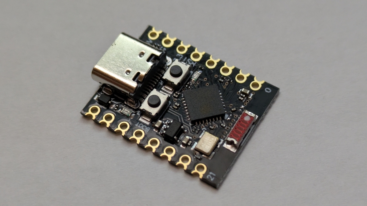
最近Amazonとかで買える小さいESP32-C3開発ボードを買ってみた
買ってみました。
一個500円くらいで小さいやつ。
技適はないので気を付けて。
仕様
- Esp32-C3 開発ボード
- チップモデル: ESP32C3FN4
- 22.52x18mm
- 1xI2C、1xSPI、2xUART、11xGPIO(PWM)、4xADC
- USB Type-C
↓こんなやつ
↓アマゾンだとこのへん


書いてあること
- Model No/Batch No/Serial : DL0053101
- Product name : development board
- Manufacturer : Shenzhen Haokeyi Trading Co.,Ltd.
- Address : 深センの住所
- E-mail/Tel : 省略
- Warning:Not for children under 3yrs.
- Business name : SUCCESS COURIER SL
- Address : スペインっぽい住所(リオ・トルメス通り1番地とか)
- E-mail/Tel : 省略
スペインの会社?が中国深センで作った?

下の赤いのは何なんでしょう?アンテナ?

「ESP32-C3」「Super Mini」って書いてある

LEDは赤色

「ESP32-C3」とよくわからないけどシリアル的なもの?

↓このへんも同じやつっぽい(1個400円~くらい)


ATtiny202 / ATtiny402のピンアサイン(簡易)
いろんな数字があって分からなくなりがちなので、基本の部分だけメモ
| ピンNo | ピン名 | 機能 | デジタル | アナログ | PWM | 割込 | SPI | I2C | UART |
|---|---|---|---|---|---|---|---|---|---|
| 1 | VCC | - | - | ||||||
| 2 | PA6 | 0 | A6 | ○ | SS | TX | |||
| 3 | PA7 | 1 | A7 | ○ | RX | ||||
| 4 | PA1 | 2 | A1 | ○ | MOSI | SDA | |||
| 5 | PA2 | 3 | A2 | ○ | ○ | MISO | SCL | ||
| 6 | PA0 | UPDI | 5 | A0 | |||||
| 7 | PA3 | 4 | A3 | ○ | SCK | ||||
| 8 | GND | - | - |
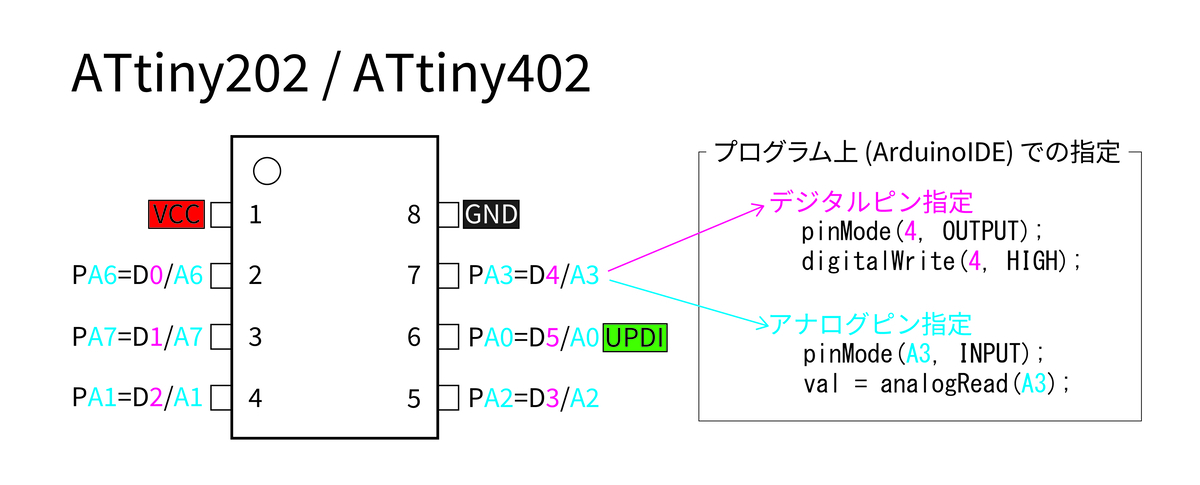
megaTinyCore https://github.com/SpenceKonde/megaTinyCore/blob/master/megaavr/extras/ATtiny_x02.md
ESP32をブラウザ上のボタンで操作する最低限のコード
概要
WiFiで接続出来てかつ、Webサーバーに簡単になっちゃうESP32なんですけど、ブラウザ上のボタンで操作したいですよね。 その部分の最低限のコードだけメモメモ。

サンプルコード
#include <WiFi.h>
#include <esp_http_server.h>

// WiFi
const char *ssid     = "XXX";
const char *password = "XXX";

// HTMLファイルの内容
static const String HTML_TEXT = R"(<!DOCTYPE html>
<html>
  <head>
    <meta charset="utf-8">
  </head>
  <body>
    <button onclick="fetch('/button_1');">ボタン1</button>
    <button onclick="fetch('/button_2');">ボタン2</button>
    <button onclick="fetch('/button_3');">ボタン3</button>
  </body>
</html>
)";

void setup() {
  Serial.begin(115200);

  // WiFi
  WiFi.begin(ssid, password);
  while (WiFi.status() != WL_CONNECTED) {
    Serial.println(".");
    delay(500);
  }
  Serial.println(WiFi.localIP());

  // Webサーバー開始
  start_server();
}

void loop() {
}

// Webサーバー開始
void start_server() {
  httpd_config_t config = HTTPD_DEFAULT_CONFIG();
  config.uri_match_fn = httpd_uri_match_wildcard; // URIのワイルドカード指定(*)を有効にする

  // ドキュメントルート用
  httpd_uri_t index_uri = {
    .uri       = "/",
    .method    = HTTP_GET,
    .handler   = index_handler,
    .user_ctx  = NULL
  };

  // ボタン用(button_xxx)
  httpd_uri_t button_uri = {
    .uri       = "/button_*",
    .method    = HTTP_GET,
    .handler   = button_handler,
    .user_ctx  = NULL
  };

  httpd_handle_t httpd = NULL;
  if (httpd_start(&httpd, &config) == ESP_OK) {
    httpd_register_uri_handler(httpd, &index_uri);
    httpd_register_uri_handler(httpd, &button_uri);
  }
}

// ドキュメントルートが表示された際の処理(ブラウザにHTMLを返す)
static esp_err_t index_handler(httpd_req_t *req) {
  httpd_resp_set_type(req, "text/html");
  httpd_resp_set_hdr(req, "Accept-Charset", "UTF-8");
  return httpd_resp_send(req, HTML_TEXT.c_str(), HTML_TEXT.length());
}

// ボタンが押された時の処理(ブラウザには何も返さない)
static esp_err_t button_handler(httpd_req_t *req) {

  // 送信されてきたURI自体で処理分岐
  String uri = req->uri;
  if(uri == "/button_1") {
    Serial.println("1来たよ");
  }
  else if(uri == "/button_2") {
    Serial.println("2押されたよ");
  }
  else if(uri == "/button_3") {
    Serial.println("3だよ");
  }

  // ブラウザには何も返さない(NULL)
  return httpd_resp_send(req, NULL, 0);
}
M5Stack ATOMS3R-CAMで画像取得
概要
カメラ付きのAtomS3(M5Stack AtomS3R-CAM)で、画像を撮影してみます。 Wifi接続でブラウザで取得するやつです。
M5AtomS3R-Camの罠
- カメラ初期化前にG18をLOW(ON)にしないと使えないよ!
- Before initializing the camera, GPIO18 must be set to low to enable power supply. This operation will also turn on the power indicator light.
")
サンプルコード
#include <WiFi.h>
#include <esp_http_server.h>
#include <esp_camera.h>

const char *ssid     = "XXXXX";
const char *password = "XXXXX";

void setup() {
  Serial.begin(115200);

  // カメラを使うにはG18(POWER_N)をONにする
  pinMode(18, OUTPUT);
  digitalWrite(18, LOW);
  delay(500); // ちょっとまってからカメラスタートしないとエラーになるっぽい

  // カメラ用パラメータ
  camera_config_t config;
  config.ledc_channel = LEDC_CHANNEL_0;
  config.ledc_timer   = LEDC_TIMER_0;
  config.pin_d0       =  3; // Y2;
  config.pin_d1       = 42; // Y3;
  config.pin_d2       = 46; // Y4;
  config.pin_d3       = 48; // Y5;
  config.pin_d4       =  4; // Y6;
  config.pin_d5       = 17; // Y7;
  config.pin_d6       = 11; // Y8;
  config.pin_d7       = 13; // Y9;
  config.pin_xclk     = 21; // XCLK;
  config.pin_pclk     = 40; // PCLK;
  config.pin_vsync    = 10; // VSYNC;
  config.pin_href     = 14; // HREF;
  config.pin_sccb_sda = 12; // SIOD;
  config.pin_sccb_scl =  9; // SIOC;
  config.pin_pwdn     = -1;
  config.pin_reset    = -1;

  config.xclk_freq_hz = 12000000; // 12MHz(20MHzだとエラーになる?)

  config.pixel_format = PIXFORMAT_RGB565;
//  config.pixel_format = PIXFORMAT_JPEG; // JPEGでの取得はサポートされていない・・・

  config.frame_size   = FRAMESIZE_QVGA; // 320x240
  config.jpeg_quality = 0;
  config.fb_count     = 2; // CAMERA_GRAB_LATEST設定時は2以上必要
  config.grab_mode    = CAMERA_GRAB_LATEST; // 最後のフレームバッファだけを取得
  config.fb_location  = CAMERA_FB_IN_PSRAM;


  // カメラ開始
  esp_err_t err = esp_camera_init(&config);
  if (err != ESP_OK) {
      Serial.printf("Camera init failed with error 0x%x", err);
      return;
  }

  // 画像反転
  sensor_t *s = esp_camera_sensor_get();
  s->set_vflip(s, 1);

  // WiFi開始
  WiFi.begin(ssid, password);
  while (WiFi.status() != WL_CONNECTED) {
      delay(500);
      Serial.println(".");
  }
  Serial.println(WiFi.localIP());

  // Webサーバー開始
  startCameraServer();
}

void loop() {}

void startCameraServer(){
  httpd_handle_t camera_httpd = NULL;
  httpd_config_t config = HTTPD_DEFAULT_CONFIG();
  httpd_uri_t capture_uri = {
    .uri       = "/",
    .method    = HTTP_GET,
    .handler   = capture_handler,
    .user_ctx  = NULL
  };
  if (httpd_start(&camera_httpd, &config) == ESP_OK) {
    httpd_register_uri_handler(camera_httpd, &capture_uri);
  }
}

uint8_t* out_jpg   = NULL;
size_t out_jpg_len = 0;

static esp_err_t capture_handler(httpd_req_t *req){
   camera_fb_t *fb = esp_camera_fb_get();
   if (!fb) {
       Serial.println("Camera capture failed");
       httpd_resp_send_500(req);
       return ESP_FAIL;
   }

   //jpeg変換
   free(out_jpg);
   frame2jpg(fb, 255, &out_jpg, &out_jpg_len);

   httpd_resp_set_type(req, "image/jpeg");
   httpd_resp_send(req, (const char *)out_jpg, out_jpg_len);
   esp_camera_fb_return(fb);

   return ESP_OK;
}
簡単!ATtiny13A/ATtiny85でサーボを回す!
ATtiny13A可愛いですよね。
ATtiny85も可愛い。
なので、サーボモーター(SG90)を回します。

ATtiny13A/ATtiny85などでサーボを動かすサンプル
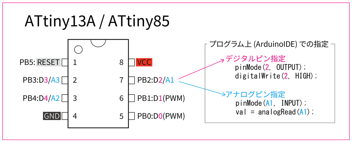
自動で動かす
- ライブラリや、余計なコード無しの最低限(コピペOK)
- 数秒ごと(50ループごと)に0度と180度を往復させるだけ
- サーボ用の信号線は右下5番(デジタルD0ピン)
- Arduino IDE + Arduino as ISP経由
#define PIN_D2 2 // ATtiny13Aの7番ピン

void setup() {
  pinMode(PIN_D2, OUTPUT);
}

void loop() {

  for(int i=0; i<50; i++){
    // 0度(HIGH=0.5ms)
    digitalWrite(PIN_D2, HIGH);
    delayMicroseconds(500); // 0.5ms
    digitalWrite(PIN_D2, LOW);
    delayMicroseconds(10000);
    delayMicroseconds(10000 - 500); // 19.5ms
  }

  for(int i=0; i<50; i++){
    // 180度(HIGH=2.4ms)
    digitalWrite(PIN_D2, HIGH);
    delayMicroseconds(2400); // 2.4ms
    digitalWrite(PIN_D2, LOW);
    delayMicroseconds(10000);
    delayMicroseconds(10000 - 2400); // 17.6ms
  }
}
ボタンON/OFFで動かす
- ボタンを押すと180度、離すと0度
#define PIN_D2 2 // ATtiny13Aの7番ピン
#define PIN_D1 1 // ATtiny13Aの6番ピン

void setup() {
  pinMode(PIN_D2, OUTPUT);
  pinMode(PIN_D1, INPUT_PULLUP);
}

void loop() {

  if (digitalRead(PIN_D1) == HIGH) // ボタンOFF
  {
    // 0度(HIGH=0.5ms)
    digitalWrite(PIN_D2, HIGH);
    delayMicroseconds(500); // 0.5ms
    digitalWrite(PIN_D2, LOW);
    delayMicroseconds(10000);
    delayMicroseconds(10000 - 500); // 19.5ms
  }
  else {
    // 180度(HIGH=2.4ms)
    digitalWrite(PIN_D2, HIGH);
    delayMicroseconds(2400); // 2.4ms
    digitalWrite(PIN_D2, LOW);
    delayMicroseconds(10000);
    delayMicroseconds(10000 - 2400); // 17.6ms
  }